Share:
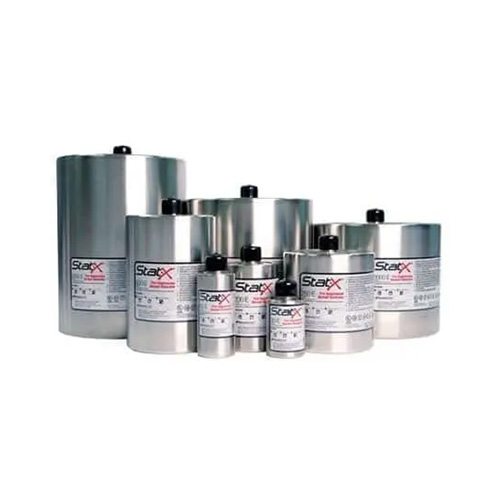
StatX Electrical Generators (vehicle)
Developed and manufactured by Kidde in Australia to meet the requirements of AS 5062, the Light Vehicle (LV) panels have a comprehensive feature set. The panels are configurable so that each fire protection system can be tailored to meet individual customer, or equipment requirements. Detection and actuation circuits as well as power supplies are supervised. The panels incorporate a manual release, audible and visual alarms and internal back-up battery (in case of loss of vehicle power) in a single IP65 rated metal enclosure. The panel also incorporates an event log capable of storing up to 600 events.
- Supports automatic fire detection, alarm and control of the fire suppression system
- Incorporates a manual discharge switch (fire system discharge) to allow the manual operation of the fire suppression system
- Display provides visual indications of system status, alarms, and faults
- Allows manual extension of the equipment shutdown delay
- Vehicle Engine Compartments
- Bus Engine Compartments
- Crane engine Compartments
- Shovels, dragline excavators, mobile tools
- Pumps and generators
- Drilling jumbos
- Forklifts
- Small to medium mobile equipment machinery spaces
Battery backup:
- Field replaceable, nonrechargeable, lithium 9 V battery
Electrical field connections:
- IP65 rated Deutsch DT series connectors
Enclosure:
- IP65 rated metal enclosure
Indications:
- Alarm: red LED
- Buzzer
- Discharged: red LED
- Fault: amber LED
- Isolated: amber LED
- Power: FAULT amber LED
- Power: ON green LED
- Shutdown: amber and red LEDs
Inputs:
- 1 detection input (supervised for open circuit and earth faults). Suitable for use with LHD cable and thermal probes
- 1 discharge confirmation input (latching)
Manual Controls:
- ACK/TEST: push button used to:
Test (panel idle): Operates all audible and visual indicators and auxiliary output
Acknowledge: Suppresses audible fault and alarm indications - Delay: Shutdown extension push button
- DIM: push button used to:
In the normal state: Adjust the brightness of the LED indicators
In FAULT state: Provides access to the faultfinding diagnostic function (common system faults) - Fault: Fault finding function to identify fault type
- Fire System Discharge: A missile-style
- Internal Battery: OFF push button
- Isolate: push button located on panel printed circuit board (PCB). Used to isolate actuation, shutdown and auxiliary outputs for testing purposes
- System Reset: Used to reset panel following fault or alarm indications
Outputs:
- 1 auxiliary output relay (singlepole, doublethrow), rated for 2 amps
- 1 discharge output (supervised for open circuit and earth faults). Capable of activating up to a maximum of 5 StatX aerosol generators, connected in a series
Configurable: For manual or automatic activation
With discharge delay periods of: 0 (default), 5, 10, 15, 20, 30 and 40 seconds OR to coincide with shutdown output operation - 1 engine shutdown relay, (singlepole, doublethrow), rated for 2 amps with selectable delay periods of 0 (default), 5, 10, 15, 20, 30, 40 and 60 seconds
Power Supply:
- Nominal 8 to 30 V DC

